Category: Sin categoría

  • Helix Pitch, What is it and What is it for?

    The Helix Pitch is not an exclusive term for helical gears, if it can be mentioned, in a screw, the helix is ​​the thread itself, in the same way, a helical drill bit for metal has two helixes, which are the channels for where the chip comes out and, what this post comes to, is the example that generates the most confusion, the case of the helix and more specifically, the helix pitch in Helical Gears.

    Helix Pitch

    To explain it, it is necessary to understand a very simple example, the case of a normal screw.

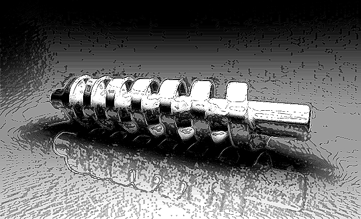
    The screw has several elements that compose it, such as: the head, the body, and the thread.

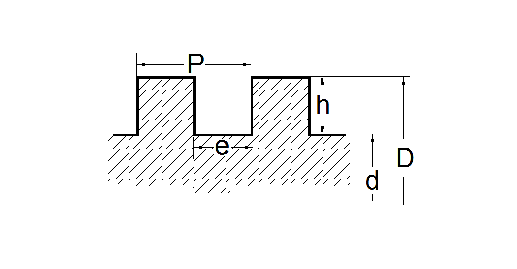
    The thread is the machining of shape, which can have multiple geometries, for example a triangle, a square, a trapezoid, a radius, etc.

    Threads is also characterized by having a constant distance for each revolution or turn of the screw.

    That is, the pitch of the thread.

    This concept, the pitch is the key to understanding what the Helix pitch is.

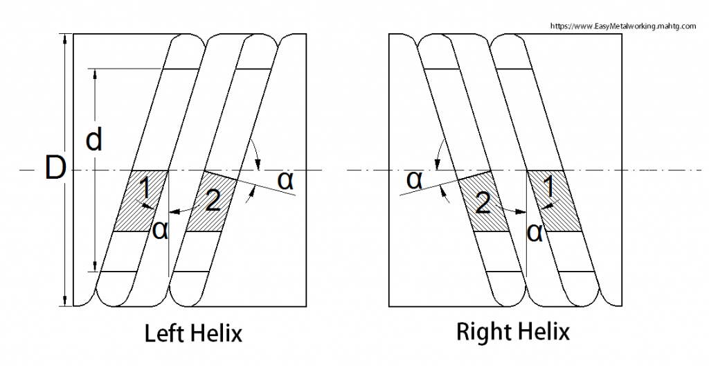
    Suppose that our screw has two starts, this means that there are two helixes, therefore the real pitch of the thread increases.

    Understanding by real pitch, the effective machining distance, or the distance between crest and crest of a helix or start.

    Continuing with the example, if the screw has three starts, in the same way, the actual pitch of the screw increases, as does the number of screw helices, which are now three.

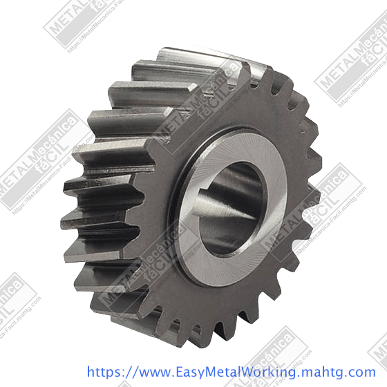
    Helix Pitch: A helical cylindrical gear is a multi-start screw.

    As has just been seen with the case of the multi-start screw, the helical cylindrical gear is a screw with several starts or helixes, therefore, with large real pitches, but with these gears, the real pitch name changes to Helix Pitch, as shown in the following graphic:

    Helix Pitch

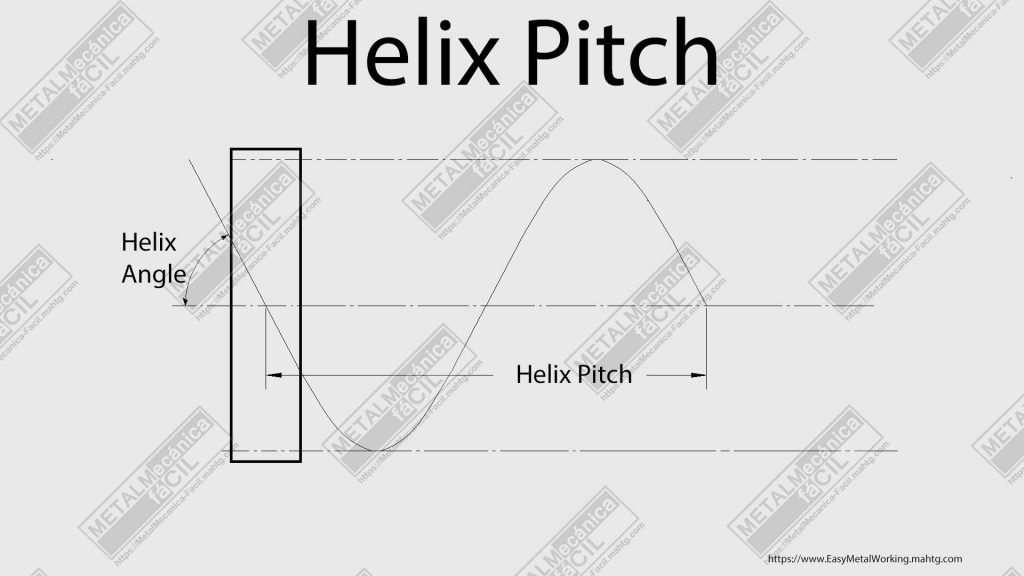
    The Helix Pitch in a helical is directly proportional to the pitch diameter of the gear, this means that if there is a small pitch diameter, the pitch tends to be small and vice versa.

    And the pitch of the helix is inversely proportional to the tangent of the helix angle.

    The formula to find the it (Hp) of a metric helical cylindrical gear is as follows:

    Hp = (Pd * PI) / tg alpha.

    Where:

    Hp: is the helix pitch gear.
    Pd: is the Pitch diameter of the gear.
    PI: is 3.1416.
    alpha: is the angle of the helix or gear tooth angle in the pitch diameter.

    You are interested in this: How to Copy a Metric Helical Gear

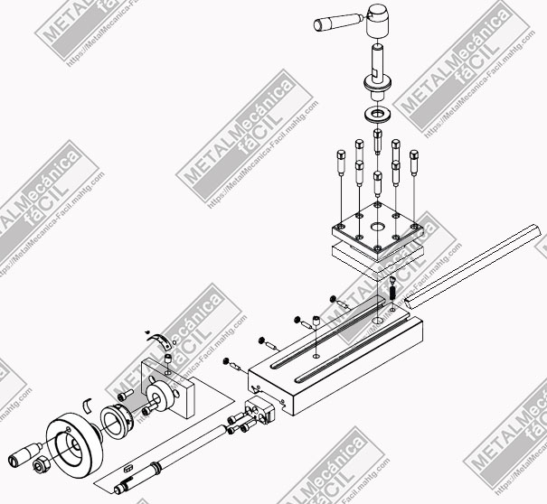
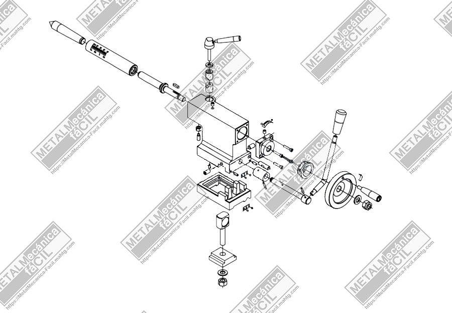
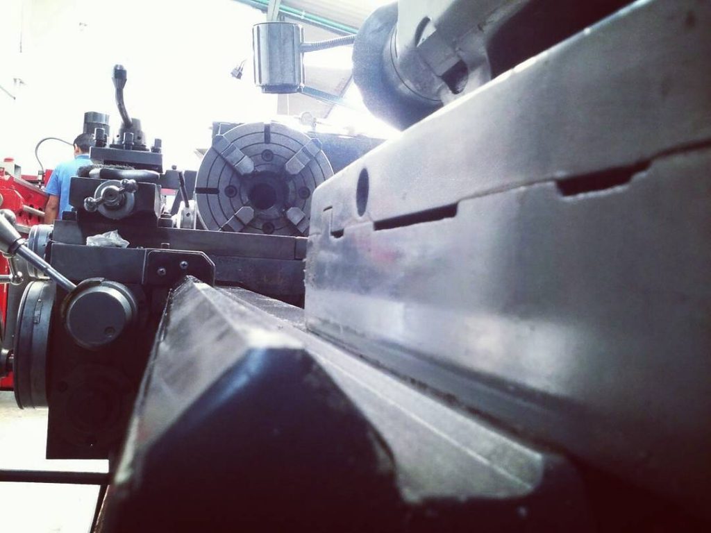
    In general, although it is not a rule, the values ​​that the calculation of the helix pitch of a helix yields are large values, which is why a relatively easy way and within reach of a workshop that has a milling machine, a dividing head and a gear train (banjo set), is precisely, execute these tracings by using the universal milling machine.

    I hope this information helps you and can be of use to you.

    If so, I ask you to please rate me with the highest star score, right here below this article.

    Please, subscribe to my YouTube Channel!

  • The Lathe Compound Rest of the Paralell Lathe

    The Lathe Compound Rest of the Universal Paralell Lathe is a sliding and rotating body that is mounted on top of the machine.

    We can also call it top slide.

    It is mainly used for turning tapers, housing the tools of the lathe, making threads and getting very fine advances that are not possible with the longitudinal slide of the lathe.

    Lathe Compound Rest

    The compound rest of the lathe is made of cast iron and has many parts, among which are:

    The compound rest swivel base, which can be rotated and is divided into sexagesimal degrees, the compound rest body, and on this, the tool post.

    In addition to these elements, we can find other accessories not more important than the previous ones, such as: the main screw or feed screw, the main nut, a gib strip, gib screws, the index ring, the tools post slide handwheel, lubrication devices and the tool post.

    Main elements of the Lathe Compound Rest

    The Compound Rest Swivel Base.
    It is made of cast iron, has two functions, the first is to serve as a guide for the compound rest body or top slide of the lathe by means of a male dovetail and the second is the possibility of turning on the base of the cross slide of the lathe thus describing angles since its base is divided into sexagesimal degrees.

    This function allows the processing of turning tapers on the lathe, but with a limitation: only we can turning tapers of a length equal to the maximum stroke allowed by this device.

    The Compound Rest Body
    Like the compound rest swivel base, it is made of cast iron, it slides over the base by means of a female dovetail and the gib strip that allows you to give it the necessary adjustment so that this element has no backlash.

    In the compound rest body, the main screw of trapezoidal thread of left sense is lodged that allows its advance or retreat, in addition it counts on the index ring and a handwheel for its manual operation.

    You might also be interested: Lathe Bed, the Most Important Part of the Machine

    Other Accessories

    • The Main or Advance Screw: It is made of alloy steel, usually with left trapezoidal thread, the pitch of this screw is a multiple of 5 to facilitate the reading of the index ring.
    • The Main Nut: It is made of high resistance bronze, it is housed in the compound rest swivel base of the lathe.
    • The Gib Strip: It is a rhomboid rule at 60°, taper at one end, it is made of cast iron, its function is to give adjustment between the compound rest swivel base and the compound rest body, this is achieved by means of two head screws located at both ends of the lathe compound rest.
    • The Index Ring: Which function is to give information about the pitch of the screw, ie gives a visual measure as to the advance or retreat of the screw of the lathe compound rest.
    • The Handwheel: Allows the manual action of the lathe compound rest screw to move this device forward or backward.
    • Lubrication devices: They are elements that allow to lodge lubricant in the parts that are in continuous friction or contact to this way to avoid their premature wearing down, these are located in strategic places of the compound rest.
    • The tool post, which is the place where we hold the tools for turning jobs. The tool post is made possible by a screw that is anchored in the upper part of the compound rest body of the lathe.

    With this information I hope to have explained in the best way the functioning and the elements that are part of the Lathe Compound Rest.

    If you think this article will help you or has helped you, please vote for the highest star rating in the bottom of this post.

    Thank you!

    Please, subscribe to my YouTube Channel!

  • The Lathe Tailstock of the Universal Parallel Lathe

    The Universal Parallel Lathe Tailstock, also known as the Moving Head, is, contrary to the lathe Headstock, a moving element. It is located on the right side of the lathe, and can be slid or moved along the entire length of the lathe bed.

    Lathe Tailstock

    Its main functions are to serve as a support in the work of turning and drilling holes, among others.

    It is built like almost all the structure of the lathe, in cast iron and is basically composed of two main parts, which are: the body and the clamp that holds the tailstock of the lathe and keeps it fixed to the bed of the machine.

    Lathe Tailstock Body Parts

    The Tailstock Spindle, which is a mobile element, is cylindrical on the outside and tapered on the inside. The taper of the inside part is standardized, usually a Morse standard. Its tapered design allows it to be made fast and easy with the accessories that are fitted to it, such as The points of the Lathe that can be fixed or mobile and the drill chuck. At the opposite end of the spindle there is a nut that allows the advance or retreat of this element. The material with which it is made is alloy steel, hardened and grinded. Some spindles have a scale engraved on their body either in millimeters or inches, an aspect that is very important.

    The Tailstock screw is a fixed element that allows the advance or retreat of the spindle, it is usually manufactured with left trapezoidal thread, it is also attached to the handwheel by means of a wedge and nuts or tapered pins. It is manufactured like the alloy steel spindle.

    In its base there is an element called “CLAMP”, which serves to fix the tailstock to the lathe bed, by means of a lever that is attached to an eccentric shaft, a screw and a nut that serves as tension and adjustment to the system, so that when it is operated, the mechanism adjusts and when it is loosened, the tailstock is free.

    Another element not less important, is a Sliding Base that is located in the lower part and that makes contact with the lathe bed. The peculiarity of this element is that it can slide or move transversely to the lathe’s axis, so that the tailstock can be off-centered in order to make or turn tapers.

    Also the lathe tailstock has a mechanism that allows the fixing or mobility of the spindle and is made up of a screw, a nut and two split bushings. This element allows the spindle to remain fixed when turning shafts and when using the points of the lathe.

    In essence, these are the main functions and parts of the lathe’s tailstock, an element without which the lathe would be of little use.

    I hope that nothing has escaped my attention, that this information can be useful to you and as always, if you liked this article, please share and rate it with the highest score in the star section below.

    Thank you very much.

    Please, subscribe to my YouTube Channel!

  • The Lathe Headstock, Important Part of the Lathe

    The Lathe Headstock is a cast iron box and is attached to the lathe bed on its left side by means of screws.

    Lathe Headstock

    The lathe headstock contains in its interior a series of elements among which are: splined shafts, gears, chains, the clutch, a reversing mechanism, a lubrication pump, bearings and perhaps, the most important part: The Spindle Lathe.

    The Headstock Spindle of the Lathe

    The lathe spindle is a hollow shaft that goes from side to side of the head in order to pass a bar that needs to be turned, for example. Its interior is conical with the standardized Morse taper, the largest diameter of the Morse taper is found at the end where the cups, chuks or plates of the lathe are placed, in general, a conical sleeve is placed in it and then the fixed point of the lathe is placed on it, that is to say the point that ends with an angle of 60°.

    The external part of the spindle is made up of couplings, wedges and threads that can accommodate or house bearings and nuts in order to allow the continuous and play-free rotary movement of this part of the machine.

    The end that protrudes from the headstock contains a coupling that allows the plates, chucks or cups of the lathe to be placed on it in a precise way.

    This element is manufactured like the other parts of the headstock lathe from special steels, alloy steels that are usually hardened and grinded, all this in order to guarantee the durability, quality and precision in the lathe.

    Some lathes may have the following elements inside the headstock:

    • Pulley: It is the mechanism that transmits the movement of the electric motor of the lathe.
    • Clutch: It is the element that allows a start both in normal and reverse gear of the lathe’s spindle. Although some lathes do not have this element.
    • Friction Brake: Enables the spindle to be stopped or braked when the clutch is not activated.
    • Fixed Gear Train.
    • Sliding Gear Train, which are those that allow the change of speeds of the lathe spindle.
    • Bearings.
    • Levers, that allow to select the speed range.

    There are also other elements on the outside and behind the fixed head of the lathe:

    • Pulley´s Belt, which transfer the movement of the electric motor to the lathe´s spindle by means of two pulleys.
    • Rear Gear Train, which communicates the movement of the lathe spindle with the lead screw.
    • Gearing Lyre, which is a piece that allows the accommodation of the rear gear train and also allows to locate or accommodate more gears.

    You may also be interested in: What is the lathe bed?

    Lubrication.

    As previously mentioned, headstock of the lathe is a box where the transmission mechanisms or converters of the electrical motion of the motor to a rotating mechanical motion of the lathe’s spindle are located, therefore, when there is a continuous motion, there is a generation of a lot of friction and therefore of heat; therefore, this box must always be lubricated. For this purpose, the fixed head is provided with eyes or bubbles where we can inspect the proper level of oil or lubricant. In addition, most lathes have a cover at the top of the fixed head, which can be removed by means of screws and observed inside, making adjustments to the clutch, or to the spindle bearings and depositing or changing the oil, which is generally a fine oil and is specified by the lathe manufacturer.

    Well friends, I trust I haven’t missed anything about this important part of the lathe.

    I hope this information has pleased you and served you well, and as always, if you liked it, please remember to rate this post with the highest score on the stars below.

    Please, subscribe to my YouTube Channel!

  • How to Read Millimeters on the Vernier Caliper

    In this post I want to share with you: How to Read Millimeters on the Vernier Caliper with an accuracy of 5 hundredths of a millimeter (0.05 mm).

    read millimeters on the vernier caliper

    Contrary to the reading of fractions of an inch, the reading of millimeters in the vernier is simpler, since in most verniers calipers the smallest unit in which the millimeter is divided is 0.05 mm. and we use the decimals of millimeter.

    The vernier caliper has two elements that intervene in the measurement, these are the ruler or main scale and the vernier scale. The main scale, as its name indicates, is graduated in all its length, with a minimum measurement unit that is the millimeter, while the vernier scale allows to take exact fractional readings of the minimum division, that is the millimeter.

    Rules for Read Millimeters on the Vernier Caliper

    Each division of the main scale is equal to ONE MILLIMETER.

    For whole measurements, you must observe the precise matching of the 0 of the vernier scale with a graduation of the main scale, in addition, the 10 of the vernier scale also matches with a graduation of the main scale.

    Example: if the 0 of the main scale matches with the 0 of the vernier scale, and also the 10 of the vernier scale matches with a graduation of the main scale, we will have a measure of 0 millimeters.

    reading millimeters 1

    If 4 graduations of the main scale matches with the 0 of the vernier scale, and the 10 of the vernier scale matches with one graduation of the main scale, the measurement is 4.0 mm.

    reading millimeters 2

    Now, if 10 graduations or 10 millimeters are exceeded, the main scale shows the 1, in the same way, when the 20 millimeters are reached, the main scale shows the 2, which means a reading of 20 millimeters and so on.

    Example:

    The 0 of the vernier scale is to the right of the 3 of the main scale plus 5 graduations or 5 millimeters, this means that there is 30mm + 5 mm, then 35 graduations of the main scale or 35 millimeters matches with the 0 of the vernier scale, therefore, the reading is 35mm.

    reading millimeters 2

    For this type of vernier caliper, the millimeter is divided into 20 parts.

    1mm./20 divisions = 0.05 mm

    This is the lowest appreciation of the vernier scale in millimeters, it is represented by a short graduation, that is, each graduation of the vernier scale is equivalent to 0.05 millimeters or 5 hundredths of a millimeter.

    2 graduations will then be: 0.05 mm + 0.05 mm = 0.1 mm or a tenth of a millimeter, which is shown by a slightly longer line, the tenth of a millimeter is represented by the number 1 on the vernier scale, two tenths are represented by the number 2, 3 tenths by the number 3 and so on.

    To take readings of tenths of a millimeter (0.1mm ) or half a tenth (0.05 mm) the only thing to keep in mind is that the graduation of the vernier scale matches exactly with a graduation of the main scale of the vernier caliper in millimeters.

    Values of Vernier Scale

    0.05mm; 0.1mm; 0.15mm; 0.2mm; 0.25mm; 0.3mm; 0.35mm; 0.4mm; 0.45mm; 0.5mm; 0.55mm; 0.6mm; 0.65mm; 0.7mm; 0.75mm; 0.8mm; 0.85mm; 0.9mm and 0.95mm

    Examples:
    3.45 mm.

    reading millimeters 4

    In the main scale, to the left of the vernier scale zero, there are 3 graduations, this means that there are 3 whole millimeters, in the vernier scale matches the graduation that is just between the four and the five with a graduation of the main scale, that is 4 tenths and a half or 0.45mm , then the result is to add the integers of the main scale plus the fraction of the vernier:

    3 + 0.45 mm. = 3.45mm.

    5.1 mm.

    5.1 millimeters

    5 graduations of the main scale to the left of the vernier scale zero, which means that there are 5 whole millimeters, in the vernier scale the graduation of the 1 matches with a graduation of the main scale, that is 0.1 mm, then the result is to add the integers of the ruler plus the fraction of the vernier:

    5 + 0,1 mm = 5,1mm

    39.95 mm.

    39.95 millimeters

    39 whole millimeters to the left of the vernier scale, plus 9.5 graduations in the vernier scale, results in 39.95 mm.

    You may also be interested in: Make a Good Measurement, Rules to Keep in Mind

    If you liked the information I just gave you then please help me with the rating below this post.
    Remember: Please, subscribe to my YouTube Channel

    Thanks a lot!

  • Make a Good Measurement, Rules to Keep in Mind

    Did you know that to measure is not only to use the measuring instrument and take the measurement, NO!, it is more than that, with these simple and basic Rules To Make A Good Measurement, we guarantee that the instrument is used properly, that it will have a long life and that the measurement we make will always be the correct one.

    Make a Good Measurement

    We must made measurements with due accuracy and care; for this purpose we must use the instrument that corresponds to the required precision. In addition, we must take in consideration some indications as the followings:

    1. Clean the surfaces of the object and the instrument before measuring.
    2. Deburr the workpieces beforehand.
    3. When taking precision measurements, pay particular attention to the reference temperature (if the workpieces have been heated by machining, they must be set aside until they recover their reference temperature).
    4. On some measuring instruments it is necessary to ensure that the measuring pressure is accurate. We never must use force.
    5. Magnetized workpieces (e.g. by magnetic clamping) must be demagnetized before measuring.
    6. Check the adjustable measuring instruments repeatedly for their zero position.
    7. Check the measuring instruments for measuring accuracy at certain intervals.

    To Make a Good Measurement Requires Care

    The instruments used to measure must be treated with great care, as this is the only way to guarantee correct measurements. In order to keep them in perfect condition, it is advisable to keep these recommendations in mind:

    1. Keep them separate from the tools (e.g. on a support lever).
    2. Place the sensitive instruments on a soft base (which can be a piece of felt or a clean cloth), protecting them from dirt.
    3. Preserve them from heat and cold.
    4. Do not drop them.
    5. Put them down carefully after use, cleaning them if necessary (remember that instruments exposed to oxidation must be treated with acid-free or grease-free oil).

    You may also be interested in: What’s a Vernier Caliper and What is it for?

    I am more than sure that with these simple Rules to Make a Good Measurement, we will obtain the best results in our work assuring with it the maximum quality.

    If you liked this information, give me a score with the stars at the bottom of the post.

    Thank you very much!

    Please, subscribe to my YouTube Channel!

  • Lathe Bed, the Most Important Part of the Machine

    The Lathe Bed is the main element of this machine tool, it is made of cast iron.

    Lathe Bed

    In its upper part it has the ways, whose main characteristic is to serve as a guide for the lathe slides and for the tailstock.

    This part of the lathe is machined, hardened and grinded to give it the highest possible precision and durability.

    The Lathe Bed, in some lathes has a portion that can be removed or disassembled, especially next to the Lathe Headstock, this part that comes out of the bed is usually known as Gap Bed.

    Some small lathes do not have Gap Bed, but most lathes do. This feature expands the turning or turning capacity of the lathe, allowing it to turn or machine parts that exceed the diameter or capacity that the bed allows under normal conditions.

    The Lathe Bed is a robust piece.

    It supports all the components of the machine tool. If you look closely at this element, it would seem that it is made of solid cast iron, but this is not the case. Its interior is hollow and has nerves or ribs that, while giving it strength and firmness, make the machine a little lighter.

    It is recommended that the bed in conjunction with the entire lathe, are perfectly level and stabilized, in order to avoid possible deformations and therefore errors when making turning jobs over time.

    An important aspect to take into account when elaborating turning works, is the care of the bed, being this the main element of the lathe, it is of capital importance its constant lubrication and cleaning, with this it is avoided its premature wear and therefore errors and deformities in the pieces elaborated in the lathe. This aspect is so important that there is a great majority of lathes that have an oil pump to exclusively lubricate this important part of the machine tool.

    You may also be interested in: How to Make the Square Thread on Lathe Machine..

    With this I arrive to the end of this article, about the Lathe Bed, I hope you liked and served it, and as always, if you liked this information, please remember to rate this post, with the highest score in the stars that are just below.

    Please, subscribe to my YouTube Channel!

  • How to Make the Square Thread on Lathe Machine.

    There is a type of thread called power transmission or high strength, its main feature is the profile of the tooth and its pitch, its main advantage: the low wear, strength and durability. Between this type of threads the most common is the Square Thread.

    Square Thread

    It is called a Square Thread because the profile of the screw thread is a perfect square.

    To avoid making screws of small diameter and big pitches or on the contrary, screws of big diameter and small pitches, this relation has been normalized or standardized and it was established that to keep a proportion between the diameter of the screw and the pitch, the latter is calculated based on the screw, and the formula to find the pitch is the following:

    P = 0.2D

    Where: P is the screw pitch and D is the outside diameter of the square threaded screw.

    Example:
    What is the correct pitch (P) for a square thread screw with an outside diameter (D) of 35 mm.?

    Then we proceed to find the pitch by using the formula:

    P = 0.2D
    P = 0.2(35)
    P = 7 mm
    The correct pitch (P) for the square screw is: 7 mm.

    Now, if we have the pitch and we want to know the diameter of the screw, then from the previous formula we must have the diameter (D), like this:

    D = P/0.2

    Let’s apply the above data to check if it is correct:
    What diameter (D) should I turn the screw with if I need the pitch (P) to be of 7 mm.?

    D = P/0.2
    D = 7/0.2
    D = 35 mm
    The correct diameter (D) is 35 mm.

    Tooth profile data of the Square Thread:

    square image 1

    D, the outside diameter of the screw, is equal to P/0.2
    P, is the pitch of the screw, is equal to 0.2D
    e, is the thickness of the thread, in the screw is equal to 0.5P
    h, is the height of the thread, in the screw it is equal to 0.5P
    d, is the inside diameter of the screw or bottom diameter, it is equal to D-2h

    It is also necessary to take into consideration the existing backlash between the screw and the nut, this is necessary for the nut to enter the screw:

    square image 2

    D’ is the diameter to turning the nut, it is equal to d+ 0.125P
    e’ is the thickness of the span of the nut, it is equal to e + 0.05 to 0.1

    Application examples of screw and nut with square thread:

    Calculate all necessary elements to produce the screw and nut with square thread in a material with a diameter of 25 mm

    SCREW:

    D = 25 mm.

    P = 0.2(D)
    P = 0.2(25)
    P = 5 mm

    e = 0.5(P)
    e = 0.5(5)
    e = 2.5 mm

    h = 0.5(P)
    h = 0.5(P)
    h = 2.5 mm

    d = D – 2(h)
    d = 25 – 2(2.5)
    d = 25 – 5
    d = 20 mm

    NUT:

    D’ = d + 0.125(P)
    D’ = 20 + 0.125(5)
    D’ = 20+0.625
    D’ = 20.625 mm

    e’ = e + 0.05
    e’ = 2.5+0.07
    e’ = 2.57

    It is also necessary to calculate the angle of inclination of the threading cutting tool.

    square thread image 4

    In the figure you can see 2 types of cutting tool when cutting the screw fillet.

    cutting tool 1: performs the finishing cut.
    cutting tool 2: performs the roughing cut.

    In this way, the two cutting tools have an angle α that allows the cutting tool not to damage the fillet of the screw when it passes through it. To calculate this angle we will take into consideration the following:

    Calculate the medium diameter of the screw (Md)
    Md = (D+d)/2

    Find the angle α of the thread’s helix like this:
    If the thread is a single start, the following formula is used:
    Tan α = P/(πMd)

    If the threading is of multiple start (n):
    Tan α = (Pn)/(πMd)

    Examples:

    Calculate the angle of the cutting tool so that it does not damage the fillet of a single start screw, pitch 5 mm, outside diameter 25 mm and inside diameter of the screw 20 mm.

    Then:
    Md = (D+d)/2
    Md = (25+20)/2
    Md = 45/2
    Md = 22.5 mm

    Tan α = P/(πMd)
    Tan α = 5/(3.1416(22.5))
    Tan α = 5/(70.686)
    Tan α = 0.07073536848
    α = tan ¯¹ (0.07073536848)
    α = 4.04609
    α = 4° 2’ 45.92’’

    Now let’s assume that the screw is a two start screw, then:
    Tan α =(Pn)/(πMd)
    Tan α = 5(2)/(3.1416(22.5))
    Tan α = 10/(70,686)
    Tan α = 0.141470729
    α = tan ¯¹ (0.141470729)
    α = 8.052240379
    α = 8° 3’ 8’

    With these formulas and this example, it is easy to calculate the Screw and Square Nut of one or multiple start thread

    If you liked the information I just gave you, then please help me with the rating below this article.

    Thank you very much!

    You may also be interested in: Conversion Between Millimeters and Inches.

    Please, subscribe to my YouTube Channel!

  • Tangent Inverse of a Value on a Calculator.

    The topic I want to deal with is about trigonometry and more specifically How to obtain the Tangent inverse of a value on a calculator?

    Tangent Inverse

    What is Tangent Inverse?

    The tangent inverse or ArcTan is the inverse function of the tangent of an angle.

    To find the arc tangent of a number, there are several ways, and we will always need any scientific calculator.

    Suppose we need to find the inverse tangent of the following number: 0.707106

    Then, using the calculator, we must keep in mind that option “D” must be enabled at the top of the screen, which means that the angle mode of the calculator is in degrees minutes and seconds.

     tangent-Inverse-image-1

    Now we must type the shift key , at the top left of the screen the letter “S” is shown.

    tangent inverse image 2

    This option activates the change function of each calculator key. Usually, the second function of each calculator key is displayed in an opaque color next to the main key.

    For the example, you must activate the second function of the calculator tangent key “tan” which is “tan⁻¹” which is the inverse tangent function. The label “tan⁻¹” will appear on the calculator display.

    tangent inverse image 3

    Now type in the value: 0.707106 and press the equal key, which corresponds to a value of 35.26435984 on the calculator screen.

    The previous number is an angle but it is in a decimal representation, so to know its value in degrees minutes and seconds, it is necessary to press again the “shift” key, and the key of degrees minutes and seconds. The calculator then shows the value 35°15’51.7″ on the screen, that is, the complete angle with its degrees, minutes and seconds.

    To know the inverse sine or the inverse cosine of any number, the procedure is the same as above, except that if it is a inverse sine, we use the sin key and its inverse, and likewise, if it is a inverse cosine, we use the cos key and its inverse.

    What to do if the calculator does not have the degrees, minutes and seconds key?

    As is the case with some cell phones or the Windows calculator?

    Then as a first step we calculate the inverse tangent of the number and proceed like this:

    ArcTan = 35.26435984

    Take the decimal part of the previous value (35.26435984) = 0.26435984 and multiply it by 60 which is equal to 15.8615904 which means that the whole part of this number, or 15, is the minutes of the angle. Up to there we would have: 35°15′.

    From the previous number (15.8615904), we take again the decimal part 0.8615904 and again it is multiplied by 60 which is equal to 51.695424 which are the seconds of the angle and can be approximated to 51.7

    Finally, the angle converted to degrees, minutes and seconds is: 35°15’51.7″

    So: ArcTan 0.707106 is 35.26435984 and is equal to 35°15’51,7″.

    This is all, really it is a simple and easy to understand item. You might also be interested: Conversion Between Millimeters and Inches

    Please, subscribe to my YouTube Channel.

  • Conversion Between Millimeters and Inches

    In the workshop it is very necessary to make Conversion Between Millimeters for handle units in both inches and millimeters, as we usually find drill bits, wrenches, measuring instruments, tools, spare parts and other elements that are in the two systems of measurement, this is where the knowledge and handling of a very important issue, this is The conversion between millimeters and inches and vice versa.

    Conversion between Millimeters and Inches

    In this article I share with you the cases and the way I do the conversions between units.

    Case 1. Conversion from Inches to Millimeters.

    To convert Inches to Millimeters, the following rule should be observed: “1 inch is equivalent to 25.4 millimeters”.

    Let’s see an example:

    What is the equivalent of 3/4 of an inch in millimeters?

    To make the conversion, I use the following method:

    conversion millimeters and inches image1

    In this case, you can simplify the inches because they are present in both the numerator and the denominator, then:

    conversion millimeters and inches image 2

    If you make: 25.4 divided by 1 is 25.4, then:

    conversion millimeters and inches image 3

    Now, if you put 1 to 25.4 mm. as the denominator, the value is not affected, as it means that 25.4 is divided by 1, which results in 25.4 being equal to:

    image 4

    Now, to multiply fractionals you proceed by multiplying numerators with numerators and denominators with denominators like this:

    image 5

    Finally, we make the division of the numerator with the denominator like this:

    conversion between millimeters and inches image 5

    This gives the final result: 19.05, then:

    image6

    Now let’s go with a case in Thousandths of an Inch:

    If we have a fraction of an inch, then this same fraction is equivalent to a number in thousandths of an inch, this corresponds to that a fraction is a division between the numerator and the denominator. Example:

    image8

    Examples of thousandths of an inch are: 0.500in., 0.750in., 0.567in., 0.001in., 1.000in., etc.

    Let’s see an example of conversion from thousandths of an inch to millimeters:

    What does 0.5625? equal in millimeters?

    The procedure is the same as in the first example:

    conversion between millimeters and inches image 6

    If we cancel the inches, we get:

    Conversion between Millimeters and Inches_10

    25.4 mm divided by 1 is 25.4 mm. Now if we multiply 0.5625″ by 25.4 mm is 14.2875 millimeters.

    Case 2. Conversion from Millimeters to Inches.

    As in the previous case, the only thing we must remember is the equivalence between millimeters and inches, that is, one inch is equivalent to 25.4 millimeters.
    Examples:

    What does 10 millimeters in inches equal?

    If we solve in the same way as to convert inches to millimeters, like this:

    Conversion between Millimeters and Inches_11

    If we cancel the millimeters because they are in both the numerator and the denominator then we get:

    Now, if we divide 1 by 25.4 = 0.03937″

    So: 10(0,03937) and if we do the multiplication normally, obtaining as result 0,3937″

    From this we can also conclude that: 1 millimeter is equivalent to 0.03937″

    Another example:

    What does 12.7 millimeters in inches equal?

    We multiply 12.7(0.03937), that is the equivalent of one millimeter to inches: then the result is: 0.500″

    These are the forms or modes I usually use when I need to do the Conversion Between Millimeters to Inch and vice versa.

    We can also convert millimeters to fractions of an inch, so I recommend you see the link that goes to this article: How to Convert Millimeters to Fractional Inch Known

    As usual, in Easy Metalworking, I share with you the tips, ideas and formulas that will help you in your machining jobs.

    If you think this article has helped you, help me continue sharing more valuable information by rating with the stars at the bottom of the post.

    Please visit my Youtube Channel.