Category: Sin categoría

  • Calculation of the Metric Helical Bevel Gear

    Hello friends, in this post I want to share: Calculation of the Metric Helical Bevel Gear.

    This is a topic that has been asked frequently on my YouTube channel and despite not having had the opportunity to manufacture a gear with these characteristics, I decided to task of consulting, understanding, and explaining this topic at least the theoretical part, and in this post, I want to convey it to you. So without further ado, let’s start!

    Known Data:

    • m: Metric Gear Module.
    • z: Number of Teeth.
    • α: Pitch Angle.
    • L: Face Width.
    • Ω: Gear Helix Angle.
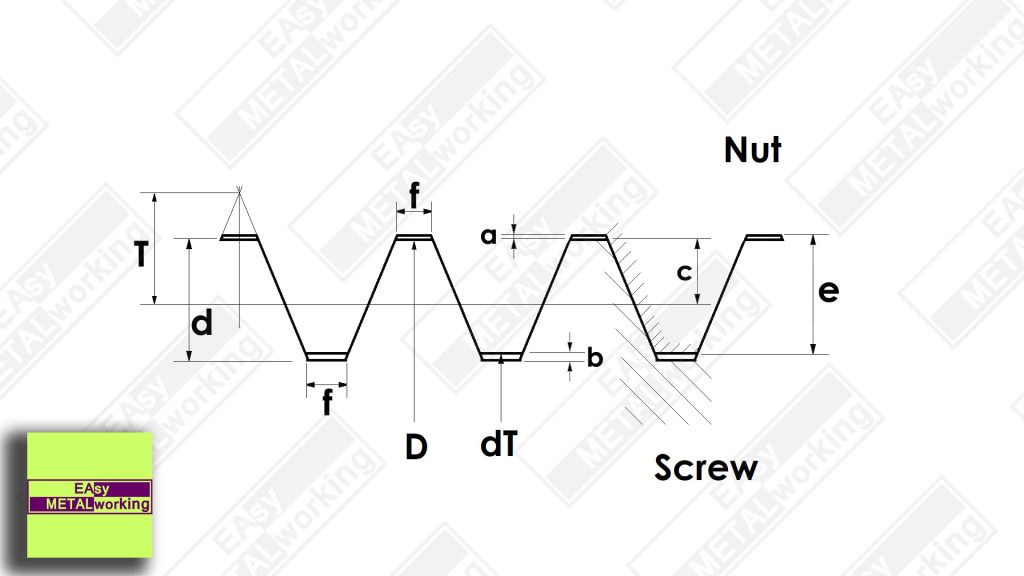
    • Cl: Chordal thickness of the cutter on the pitch circle, at the larger end of the gear.
    • Cs: Chordal thickness of the cutter tooth on the pitch circumference, at the smaller end of the gear.

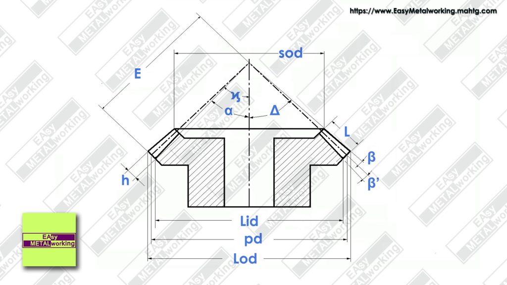
    Formulas for Bevel Gear

    These are the machining formulas for the Bevel Gear:

    1. Apparent module (am)
      am = m / cos Ω
    2. Pitch diameter (pd)
      pd = am * z
    3. Larger outside diameter (Lod)
      Lod = pd + (2 * m * cos α)
    4. Cone distance (E)
      E = pd / (2 * sin α )
    5. Larger inside diameter (Lid)
      Lid = pd – (1.157 * 2 * m * Cos α)
    6. Smaller outside diameter (sod)
      sod = Lod (E – L) / E
    7. Tooth height (h)
      h = 2.167 * m
    8. Angle corresponding to the module (β)
      tan β = m / E
    9. Angle corresponding to the bottom of the toothing clearance (β’)
      tan β’ = 0,157 (m / E)
    10. Half angle of the face cone (Δ)
      Δ = α + β
    11. Dividing Head Tilt Angle (ϗ)
      ϗ = α – (β + β’)
    12. Lead (L)
      L = π * pd / tan Ω
    Calculation of the metric helical bevel gear

    EXAMPLE:

    Make the Calculation of the Metric Helical Bevel Gear with the following data:

    • Metric Module (m) = 4
    • Number of teeth (z) = 16
    • The angle at the center of the gear (α) = 37° 20′
    • Face Width (L) = 19 millimeters
    • Gear helix angle (Ω) = 30°
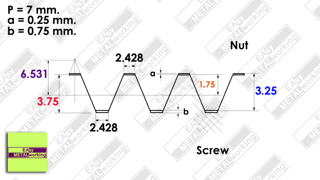
    • The chordal thickness of the cutter on the pitch circle, at the larger end of the gear (Cl) = 5.8 millimeters
    • The chordal thickness of the cutter tooth on the pitch circumference, at the smaller end of the gear (Cs) = 4.3 millimeters

    These last two values: Cl and Cs are taken from the respective cutters. I will talk about this topic later.

    Now let’s go with the calculations:

    In the first instance, we will calculate everything related to the geometry of the bevel gear, which does not differ much from the metric bevel gear with straight teeth.

    1. Apparent module (am)
      am = m / cos Ω
      am = 4 / cos 30°
      am = 4 / 0.86603
      am = 4.618
    2. Pitch diameter (pd)
      pd = am * z
      pd = 4.618 * 16
      pd = 73.90 millimeters.
    3. Larger outside diameter (Lod)
      Lod = pd + (2 * m * cos α)
      Lod = 73.90 + (2 * 4 * cos 37° 20′)
      Lod = 73.90 + (2 * 4 * 0.7951)
      Lod = 73.90 + (2 * 3.1804)
      Lod = 73.90 + 6.3609
      Lod = 80.264 millimeters
    4. Cone distance (E)
      E = pd / (2 * sin α )
      E = 73.90 / (2 * sin 37° 20′)
      E = 73.90 / (2 * 0.60645)
      E = 73.90 / 1.21290
      E = 60.92 millimeters
    5. Larger inside diameter (Lid)
      Lid = pd – (1.157 * 2 * m * Cos α)
      Lid = 73.90 – (1.157 * 2 * 4 * Cos 37° 20′)
      Lid = 73.9 – (1.157 * 2 * 4 * 0.7954)
      Lid = 73.9 – (1.157 * 2 * 3.1816)
      Lid = 73.9 – (1.157 * 6.3632)
      Lid = 73.9 – 7.3622
      Lid = 63.537 millimeters
    6. Smaller outside diameter (sod)
      sod = Lod (E – L) / E
      sod = 80.26 (60.92 – 19) / 60.92
      sod = 80.26 (41.92) / 60.92
      sod = 3,364.4992 / 60.92
      sod = 55.29 millimeters.
    7. Tooth height (h)
      h = 2.167 * m
      h = 2.167 * 4
      h = 8.668 millimeters
    8. Angle corresponding to the module (β)
      tan β = m / E
      tan β = 4 / 60.92
      tan β = 0.065659
      β = tan⁻¹ 0.065659
      β = 3.7566°
      β = 3° 45′ 23.91″
    9. Angle corresponding to the bottom of the toothing clearance (β’)
      tan β’ = 0,157 (m / E)
      tan β’ = 0,157 (4 / 60.92)
      tan β’ = 0.157 * 0.065659
      tan β’ = 0.010308463
      β’ = tan⁻¹ 0.010308463
      β’ = 0.590610°
      β’ = 0° 35′ 26.19″
    10. Half angle of the face cone (Δ)
      Δ = α + β
      Δ = 37° 20′ + 3° 45′
      Δ = 41° 5′
    11. Dividing Head Tilt Angle (ϗ)
      ϗ = α – (β + β’)
      ϗ = 37° 20′ – (3° 45′ + 0° 35′)
      ϗ = 37° 20′ – 4° 20′
      ϗ = 33°
    12. Lead (L)
      L = π * pd / tan Ω
      L = (3.1416 * 73.9) / tan 30°
      L = 232.164 / 0.57735
      L = 402.119 millimeters

    With these data, it is possible to carry out the turning part, the inclination of the dividing head, and search for the series of gears in the banjo to mount on the universal milling machine.

    As a second step, we go with the calculation of the angle of rotation of the dividing head and the deviation for the correct cutting of the teeth of the helical bevel gear.

    Machining formulas:

    1. Tooth Variation Coefficient (Χ)
      X = (E – L) / E
    2. Milling cutter module (mc)
      mc = X * m
    3. Equivalent helical pitch diameter (Pd)
      Pd = pd / cos α
    4. Number of teeth of the equivalent helical gear (eZ)
      eZ = Pd / (m * Cos² Ω)
    5. The apparent pitch at the larger end of the gear (ap)
      ap = π * m / Cos Ω
    6. Pitch taper radius at the larger end of the gear (TR)
      TR = pd / (2 * Sin α)
    7. The rotation angle of the gear (ra)
      ra = (57.3 / pd)*((ap/2) – (TR / (L * Cos Ω) * (Cl – Cs)))
    8. Divisions in the dividing head of the milling machine: (Dd)
      Dd = 40 / z
      40 is the dividing head ratio
    9. Number of degrees for a full rotation of the dividing head (Nd)
      Nd = 9°
    10. Dividing head holes (dhh)
      dhh = q * (ra / Nd)
    11. Readjustment calculation (Rc)
      Rc = (Cl / 2 * Cos Ω) – ((Cl – Cs) * TR / 2 * L * cos Ω)

    Now apply the previous formulas in the example:

    1. Tooth Variation Coefficient (Χ)
      X = (E – L) / E
      X = (60.92 – 19) / 60.92
      X = 41.92 / 60.92
      X = 0.688
    2. Milling cutter module (mc)
      mc = X * m
      mc = 0.688 * 4
      mc = 2.75
    3. Equivalent helical pitch diameter (Pd)
      Pd = pd / cos α
      Pd = 73.90 / cos 37° 20′
      Pd = 73.90 / 0.7954
      Pd = 92.909 millimeters
    4. Number of teeth of the equivalent helical gear (eZ)
      eZ = Pd / (m * Cos² Ω)
      eZ = 92.9 / 4 * Cos ² 30°
      eZ = 92.9 / 4 * 0.86603 ²
      eZ = 92.9 / 4 * 0.75
      eZ = 92.9 / 3
      eZ = 30.96 For the Number of teeth of the equivalent helical gear Zf, cutter number 5 corresponds
    5. The apparent pitch at the larger end of the gear (ap)
      ap = π * m / Cos Ω
      ap = 3.1416 * 4 / cos 30°
      ap = 3.1416 * 4 / 0.86603
      ap = 12 .5664 / 0.86603
      ap = 14.5103
    6. Pitch taper radius at the larger end of the gear (TR)
      TR = pd / (2 * Sin α)
      TR = 73.90 /(2 * Sin 37° 20′)
      TR = 73.90 /(2 * 0.60645)
      TR = 73.9 / 1.2129
      TR = 60.928

    Here is a small parenthesis. The value “Cl” cordal thickness of the cutter on the pitch circle, at the larger end of the gear, is taken in the milling cutter with a special gauge, or it can be done approximately with a conventional vernier, and in this case, it is done in the milling cutter module 4, and the value is 5.8 millimeters,

    In the same way, for the chordal thickness of the cutter on the pitch circle, at the smaller end of the gear.: “Cs” is made in the cutter module 2.75 that We calculated in the point: “cutter Module and that gave a value: of 2.75 and whose value is: 4.3 millimeters.

    1. The rotation angle of the gear (ra)
      ra = (57.3 / pd)*((ap/2) – (TR / (L * Cos Ω) * (Cl – Cs)))
      ra = 57.3 / 73.9 ((14.51/2) – (60.92/19 * Cos 30°)(5.8 – 4.3))
      ra = 0.775 (7.25 – (60.92/19 * 0.86603) * 1.5)
      ra = 0.775 (7.25 – (60.92/16.45) * 1.5)
      ra = 0.775 (7.25 – (3.703 * 1.5))
      ra = 0.775 (7.25 – 5.55)
      ra = 0.775 (1.7)
      ra = 1.31
    1. Divisions in the dividing head of the milling machine: (Dd)
      Dd = 40 / z
      Dd = 40/16
      Dd = 2 turns, 1 hole in the plate of 2 holes. Now amplifying the fraction by 14 times
      Dd = 2 turns, 14 holes in the plate of 28 holes.
    2. Number of degrees for a full rotation of the dividing head (Nd)
      Nd = 9°
    3. Dividing head holes (dhh)
      dhh = q * (ra / Nd)
      dhh = 28 * (1.31 / 9°)
      dhh = 28 * 0.145
      dhh = 4.06 holes or 4 holes of the dividing head plate.
    4. Readjustment calculation (Rc)
      Rc = (Cl / 2 * Cos Ω) – ((Cl – Cs) * TR / 2 * L * cos Ω)
      Rc = (5.8/2*Cos 30°) – ((5.8- 4.3) *60.92/219cos 30°)
      Rc = (5.8/20.86603) – ((1.5)60.92/38*0.86603)
      Rc = (5.8/1.73) – (91.38/32.9)
      Rc = 3.35 – 2.77
      Rc = 0.58 millimeters.

    For gear milling it is recommended:

    When we have to do the Calculation of the Metric Helical Bevel Gear, we must keep in mind:

    • Tilt the dividing head 33° and set the dividing for 2 turns, 14 holes on the 28-hole plate.
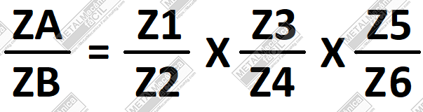
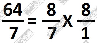
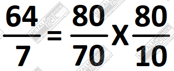
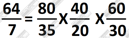
    • Assemble the gear train,
    • Place the milling head vertically and mount the Modular spike cutter,
    • Mill the teeth to the depth in the largest diameter of 8.7 mm.
    • Rotate the piece clockwise with the head to the left 4 holes,
    • move the table outward 0.6 millimeters, and mill the faces of the teeth.
    • Rotate the part counterclockwise 8 holes and move the table 1.2mm to mill the faces of the teeth.

    You may be interested in How to Copy a Metric Helical Gear

    With this information, I hope to have explained the best way the features, concepts, and information about the Calculation of the Metric Helical Bevel Gear

    If you think this note can help you or has been useful, I ask you to please vote with the highest star rating at the bottom of this article.

    Thank you very much!

    Please, subscribe to my YouTube Channel!

  • Exercises of Inches to Millimeters Conversion

    Hello internet friends, in this post I want to share with you some examples or exercises of inches to millimeters conversion. Remembering the general rule of conversion from inches to millimeters and vice versa, it goes as follows:

    1 inch is equivalent to 25.4 millimeters.

    Exercises of Inches to Millimeters Conversion

    Now let’s take a look at some exercises of inches to millimeters conversion:

    1. What is 3/4 inch equivalent to in millimeters?
      Solution:
      We need to multiply 3/4 inch times 25.4 which gives us: (3 x 25.4) / 4 =
      76.2 / 4
      = 19.05 mm.
      Therefore, 3/4 in. is equivalent to 19.05 mm.
    2. What is 1 inch equivalent to in millimeters?
      Solution:
      We multiply 1-inch times 25.4 mm.
      This gives us: 1 x 25.4 = 25.4 mm.
      Therefore, 1 inch is equivalent to 25.4 mm.
    3. What is 1/16 inch equivalent to in millimeters?
      Solution:
      We multiply 1/16 inch. times 25.4 mm.
      This gives us: (1 x 25.4) / 16 = 25.4 / 16 = 1.5875 mm.
      Therefore, 1/16 inch is equivalent to 1.5875 mm.
    4. What is 1/2 inch equivalent to in millimeters?
      Solution:
      We multiply 1/2 inch times 25.4 mm.
      This gives us: (1 x 25.4) / 2 = 25.4 / 2 = 12.7 mm.
      Therefore, 1/2 inch is equivalent to 12.7 mm.
    5. What is 9/64 inch equivalent to in millimeters?
      Solution:
      We multiply 9/64 inches times 25.4 mm.
      This gives us: (9 x 25.4) / 64 = 228.6 / 64 = 3.571875 mm.
      Therefore, 9/64 inches is equivalent to 3.571875 mm.
    6. What is 127/128 inch equivalent to in millimeters?
      Solution:
      We multiply 127/128 inches times 25.4 mm
      This gives us: (127 x 25.4) / 128 = 3225.8 / 128 = 25.2015625 mm.
      Therefore, 127/128 inches is equivalent to 25.2015625 mm.
    7. What is 15/32 inch equivalent to in millimeters?
      Solution:
      We multiply 15/32 inch times 25.4 mm
      This gives us: (15 x 25.4) / 32 = 381 / 32 = 11.90625mm
      Therefore, 15/32 inches is equivalent to 11.90625 mm.
    8. What is 5/8 inch equivalent to in millimeters?
      Solution:
      We multiply 5/8 inch times 25.4 mm.
      This gives us: (5 x 25.4) / 8 = 127 / 8 = 15.875 mm.
      Therefore, 5/8 in. is equivalent to 15.875mm.”

    Conversion from thousandths of an inch to millimeters

    The same procedure applies when inches are expressed in decimal numbers, for example, 1.345 inches; 0.750 inches; 2.000 inches, etc.
    Let’s see some examples:

    1. What is 0.625 inches in millimeters?
      Solution:
      We multiply 0.625 inches times 25.4 mm.
      This is: 0.625(25.4) = 15.875 mm.
      0.625 inch is equivalent to 15.875 mm.
    2. What are 0.500 inches in millimeters?
      Solution:
      We multiply 0.500 inches times 25.4 mm.
      This is: 0.500(25.4) = 12.7 mm.
      0.500 inches is equivalent to 12.7 mm.
    3. What are 0.999 inches in millimeters?
      Solution:
      We multiply 0.999 times by 25.4 mm.
      This is: 0.999(25.4) = 25.3746 mm.
      0.999 inches is equivalent to 25.3746 mm.
    4. What are 2.283 inches in millimeters?
      Solution:
      We multiply 2.283 inches times 25.4 mm.
      This is: 2.283(25.4) = 57.9882 mm.
      2.283 inches is equivalent to 57.9882 mm.
    5. What are 4.3455 inches in millimeters?
      Solution:
      We multiply 4.3455 inches times 25.4 mm.
      This is: 4.3455(25.4) = 110.3757 mm.
      4.3455 inches is equivalent to 110.3757 mm.

    To conclude, with these examples and exercises, you can see that it is very simple to convert inches to millimeters.

    If you found this information helpful, please rate it below.

    Thank you!

    You may also be interested in How to Convert Millimeters to Known Fractional Inches?

    Please, subscribe to my YouTube Channel!

  • ISO Metric Thread Pitch Table Chart

    Below, I share with you a ISO Metric Thread Pitch Table Chart.

    It includes the thread, the nominal bolt diameter (D), the pitch (p), the drill bit diameter (Db) for making nuts, the thread depth (H), the double thread depth, and the 30° Thread Depth (H30°). The latter two are useful for determining the height or depth of the thread on the lathe machine, using either only the cross slide or the top slide tilted at 30°.

    ISO Metric Thread Pitch Table Chart

    All dimensions in the ISO Metric Thread Pitch Table Chart are in millimeters.

    In addition, it’s necessary to know the formulas used in the table chart, particularly the drill bit diameter (Db), the thread depth (H), and the 30° thread depth:

    Db = D – p
    H = 0.6495(p)
    H30° = 0.6495(p)/cos 30°

    Metric Thread Table Chart

    ISO ThreadNominal bolt diameter (D)PitchDrill bit diameter (Db)Thread depth (H)Double thread depth30° Thread Depth (H30°)
    M2 X 0.420.401.60.25980.51960.2999912
    M3 X 0.2530.252.750.1623750.324750.1874945
    M3 X 0.530.502.50.324750.64950.374989
    M4 X 0.3540.353.650.2273250.454650.2624923
    M4 X 0.740.703.30.454650.90930.5249846
    M5 X 0.550.504.50.324750.64950.374989
    M5 X 0.850.804.20.51961.03920.5999824
    M6 X 0.560.505.50.324750.64950.374989
    M6 X 1.061.050.64951.2990.749978
    M7 X 0.7570.756.250.4871250.974250.5624835
    M7 X 1.071.060.64951.2990.749978
    M8 X 0.7580.757.250.4871250.974250.5624835
    M8 X 1.081.070.64951.2990.749978
    M8 X 1.2581.256.750.8118751.623750.9374725
    M9 X 1.091.080.64951.2990.749978
    M9 X 1.2591.257.750.8118751.623750.9374725
    M10 X 0.75100.759.250.4871250.974250.5624835
    M10 X 1.0101.090.64951.2990.749978
    M10 X 1.25101.258.750.8118751.623750.9374725
    M10 X 1.50101.508.50.974251.94851.124967
    M11 X 1.0111.0100.64951.2990.749978
    M11 X 1.25111.259.750.8118751.623750.9374725
    M11 X 1.50111.509.50.974251.94851.124967
    M12 X 1.0121.0110.64951.2990.749978
    M12 X 1.25121.2510.750.8118751.623750.9374725
    M12 X 1.50121.5010.50.974251.94851.124967
    M12 X 1.75121.7510.251.1366252.273251.312461499
    M13 X 1.25131.2511.750.8118751.623750.9374725
    M13 X 1.50131.5011.50.974251.94851.124967
    M13 X 1.75131.7511.251.1366252.273251.312461499
    M14 X 1.0141.0130.64951.2990.749978
    M14 X 1.25141.2512.750.8118751.623750.9374725
    M14 X 1.50141.5012.50.974251.94851.124967
    M14 X 1.75141.7512.251.1366252.273251.312461499
    M14 X 2.0142.0121.2992.5981.499955999
    M15 X 1.25151.2513.750.8118751.623750.9374725
    M15 X 1.50151.5013.50.974251.94851.124967
    M15 X 2.0152.0131.2992.5981.499955999
    M16 X 1.0161.0150.64951.2990.749978
    M16 X 1.25161.2514.750.8118751.623750.9374725
    M16 X 1.50161.5014.50.974251.94851.124967
    M16 X 2.0162.0141.2992.5981.499955999
    M18 X 1.25181.2516.750.8118751.623750.9374725
    M18 X 1.50181.5016.50.974251.94851.124967
    M18 X 2.0182.0161.2992.5981.499955999
    M18 X 2.50182.5015.51.623753.24751.874944999
    M20 X 1.50201.5018.50.974251.94851.124967
    M20 X 2.0202.0181.2992.5981.499955999
    M20 X 2.5202.5017.51.623753.24751.874944999
    M22 X 1.50221.5020.50.974251.94851.124967
    M22 X 2.0222.0201.2992.5981.499955999
    M22 X 2.50222.5019.51.623753.24751.874944999
    M24 X 1.5241.5022.50.974251.94851.124967
    M24 X 2.0242.0221.2992.5981.499955999
    M24 X 3.0243.0211.94853.8972.249933999
    M27 X 1.50271.5025.50.974251.94851.124967
    M27 X 2.0272.0251.2992.5981.499955999
    M27 X 3.0273.0241.94853.8972.249933999
    M30 X 2.0302.0281.2992.5981.499955999
    M30 X 3.0303.0271.94853.8972.249933999
    M30 X 3.5303.5026.52.273254.54652.624922999
    M33 X 2.0332.0311.2992.5981.499955999
    M33 X 3.0333.0301.94853.8972.249933999
    M33 X 3.5333.5029.52.273254.54652.624922999
    M36 X 2.0362.0341.2992.5981.499955999
    M36 X 3.0363.0331.94853.8972.249933999
    M36 X 4.0364.0322.5985.1962.999911999
    M39 X 2.0392.0371.2992.5981.499955999
    M39 X 3.0393.0361.94853.8972.249933999
    M39 X 4.0394.0352.5985.1962.999911999

    You may be interested in: Metric Trapezoidal Thread – Machining Calculations.

    With this information, I hope to have explained the best way the features, concepts, and information about the ISO Metric Thread Pitch.

    If you think this note can help you or has been useful, I ask you to please vote with the highest star rating at the bottom of this article.

    Thank you very much!

    Please, subscribe to my YouTube Channel!

  • Division Table Chart for the Dividing Head

    Hello friends, in this post I want to share with you information and a table chart for the dividing head.
    Below I show a Division Table Chart for the Dividing Head considering the following aspects:

    • They are performed with the normal or conventional dividing heads ratio which is 40 to 1.
    • The drilled plates are the standard type, meaning the most common ones in the dividing heads which are:
      • Plate No.1: 24; 25; 28; 30; 37; 38; 39; 41; 42; 43 holes and
      • Plate No.2: 46; 47; 49; 51; 53; 54; 57; 58; 59; 62; 66 holes.
    Division Table Chart for the Dividing Head

    In the table chart, we have to locate the number of divisions we want to perform and in the row, the number of turns of the dividing head’s crank, the number of holes or drilled holes in the plate, and the number of holes to be located with the dividing heada’s arms are located.

    Divisions Table Chart No. 1

    Number of Divisions for MakingNumber of Turns of the Dividing Head’s CrankNumber of Holes in the PlateHoles
    220
    313248
    410
    58
    662416
    752820
    85
    945424
    104
    1136642
    123248
    133393
    1424942
    1522416
    1622412
    1723412
    1825412
    192384
    202
    2114238
    2216654
    2314634
    2412416
    2512515
    2613921
    2715426
    2814218
    2915822
    301248
    3116218
    321287
    3316614
    341346
    351284
    361546
    371373
    381382
    391391
    401
    414140
    424240
    434340
    446660
    455448
    464640
    474740
    482420
    494940
    502520
    515140
    523930
    535340
    545440
    556648
    562820
    575740
    585840
    595940
    604228
    626240
    642415
    653924
    666640
    683420
    702816
    725430
    743720
    753016
    763820
    783920
    803417
    824120
    844220
    853416
    864320
    886630
    905424
    924620
    944720
    953816
    962410
    984920
    1002510
    1025120
    1043915
    1054216
    1065320
    1085420
    1106624
    1122810
    1145720
    1154616
    1165820
    1185920
    1206622
    1246220
    125258
    1303912
    1326620
    1355416
    1363410
    140288
    1445415
    1455816
    1483710
    150308
    1523810
    1556216
    1563910
    160287
    1644110
    1656616
    1684210
    170348
    1724310
    1766615
    1805412
    1844610
    185378
    1884710
    190388
    192245
    195398
    1964910
    200306
    2045110
    205418
    210428
    2125310
    215438
    2165410
    2206612
    224285
    2285710
    230468
    2325810
    235478
    2365910
    2406611
    245498
    2486210
    250254
    255518
    260396
    2646610
    270548
    272345
    280284
    290588
    296375
    300304
    304385
    310628
    312395
    320243
    328415
    330668
    336425
    340344
    344435
    360546
    370374
    376475
    380384
    390394
    392495
    400303

    You may also be interested in: Gear Train – Concepts and Calculation.

    There are also other types of dividing heads that are very common and are accompanied by 3 divided plates, as follows:

    Plate No.1: 15; 16; 17; 18; 19; 20 holes,
    Plate No.2: 21; 23; 27; 29; 31; 33 holes and
    Plate No.3: 37; 39; 41; 43; 47 and 49 holes.

    Divisions Table Chart No. 2

    Number of Divisions for MakingNumber of Turns of the Dividing Head’s CrankNumber of Holes in the PlateHoles
    220
    313155
    410
    58
    661510
    752115
    85
    94188
    104
    1133321
    123155
    133393
    1422118
    1521510
    162168
    172176
    182184
    192192
    202
    2112119
    2213327
    2312317
    2411510
    251159
    2613921
    2712713
    281219
    2912911
    301155
    311319
    321164
    331337
    341173
    351213
    361182
    371373
    381191
    391391
    401
    414140
    422120
    434340
    443330
    451816
    462320
    474740
    481815
    494940
    501512
    523930
    542720
    553324
    562115
    582920
    601510
    623120
    641610
    653924
    663320
    681710
    702112
    721810
    743720
    75158
    761910
    783920
    80168
    824120
    842110
    85178
    864320
    883315
    90188
    922310
    944720
    95198
    984920
    100156
    1043915
    105218
    1082710
    1103312
    115238
    1162910
    120155
    1243110
    1303912
    1323310
    135278
    136175
    140216
    145298
    1483710
    150154
    152195
    155318
    1563910
    160205
    1644110
    165338
    168215
    170174
    1724310
    180184
    184235
    185378
    1884710
    190194
    195398
    1964910
    200153
    205418
    210214
    215438
    216275
    220336
    230234
    232295
    235478
    240183
    245498
    248315
    260396
    264335
    270274
    280213
    290294
    296375
    300152
    310314
    320162
    328415
    330334
    340172
    344435
    360182
    370374
    376475
    380192
    390394
    392495
    400202

    If this information about Division Table Chart for the Dividing Head was helpful to you, please rate with the stars at the end of the post.

    And remember to share…

    Thank you very much.

    Please, subscribe to my YouTube Channel!

  • Conversion of Inch Fractions to Thousandths of an Inch

    Hello Friends, in the workshop it’s very useful to have certain information and in this post I want to share with you a Table chart with Conversion of Inch Fractions to Thousandths of an Inch which can save you time and quickly access this information.

    Conversion of Inch Fractions to Thousandths

    The table chart consists of three columns. In the first column you will find all the vernier measurements in inch fractions with an accuracy of 1/128 in., so there will be 128 rows, each separated from the next or previous one by 1/128 of an inch.

    In the second column of the Conversion Table Chart of inch Fractions to Thousandths of an Inch, you will find the equivalence of each inch fraction to thousandths of an inch, and this is nothing more than the result of dividing the numerator of the fraction by the denominator of the fraction, for example, if the inch fraction is 1/2 in., its value in thousandths of an inch is 1 divided by 2 which is equal to 0.500 in.

    And finally, there’s the third column, in this one, the equivalence of the numbers in inches to millimeters is shown, which is nothing more than multiplying any value either from the first column or from the second column by 25.4

    Table Chart with Conversion of Inch Fractions to Thousandths of an Inch

    Inch FractionsThousandths of an InchMillimeters
    1/1280.00780.19
    1/640.01560.39
    3/1280.02340.59
    1/320.03130.79
    5/1280.03910.99
    3/640.04691.19
    7/1280.05471.39
    1/160.06251.58
    9/1280.07031.78
    5/640.07811.98
    11/1280.08592.18
    3/320.09382.38
    13/1280.10162.58
    7/640.10942.78
    15/1280.11722.98
    1/80.12503.18
    17/1280.13283.37
    9/640.14063.57
    19/1280.14843.77
    5/320.15633.97
    21/1280.16414.17
    11/640.17194.37
    23/1280.17974.56
    3/160.18754.76
    25/1280.19534.96
    13/640.20315.16
    27/1280.21095.36
    7/320.21885.56
    29/1280.22665.75
    15/640.23445.95
    31/1280.24226.15
    1/40.25006.35
    33/1280.25786.55
    17/640.26566.75
    35/1280.27346.95
    9/320.28137.14
    37/1280.28917.34
    19/640.29697.54
    39/1280.30477.74
    5/160.31257.94
    41/1280.32038.14
    21/640.32818.33
    43/1280.33598.53
    11/320.34388.73
    45/1280.35168.93
    23/640.35949.13
    47/1280.36729.33
    3/80.37509.53
    49/1280.38289.72
    25/640.39069.92
    51/1280.398410.12
    13/320.406310.32
    53/1280.414110.52
    27/640.421910.72
    55/1280.429710.91
    7/160.437511.11
    57/1280.445311.31
    29/640.453111.51
    59/1280.460911.71
    15/320.468811.91
    61/1280.476612.10
    31/640.484412.30
    63/1280.492212.50
    1/20.500012.70
    65/1280.507812.90
    33/640.515613.10
    67/1280.523413.30
    17/320.531313.49
    69/1280.539113.69
    35/640.546913.89
    71/1280.554714.09
    9/160.562514.29
    73/1280.570314.49
    37/640.578114.68
    75/1280.585914.88
    19/320.593815.08
    77/1280.601615.28
    39/640.609415.48
    79/1280.617215.68
    5/80.625015.88
    81/1280.632816.07
    41/640.640616.27
    83/1280.648416.47
    21/320.656316.67
    85/1280.664116.87
    43/640.671917.07
    87/1280.679717.26
    11/160.687517.46
    89/1280.695317.66
    45/640.703117.86
    91/1280.710918.06
    23/320.718818.26
    93/1280.726618.45
    47/640.734418.65
    95/1280.742218.85
    3/40.750019.05
    97/1280.757819.25
    49/640.765619.45
    99/1280.773419.65
    25/320.781319.84
    101/1280.789120.04
    51/640.796920.24
    103/1280.804720.44
    13/160.812520.64
    105/1280.820320.84
    53/640.828121.03
    107/1280.835921.23
    27/320.843821.43
    109/1280.851621.63
    55/640.859421.83
    111/1280.867222.03
    7/80.875022.23
    113/1280.882822.42
    57/640.890622.62
    115/1280.898422.82
    29/320.906323.02
    117/1280.914123.22
    59/640.921923.42
    119/1280.929723.61
    15/160.937523.81
    121/1280.945324.01
    61/640.953124.21
    123/1280.960924.41
    31/320.968824.61
    125/1280.976624.80
    63/640.984425.00
    127/1280.992225.20
    11.000025.40

    You may also be interested in: Machining Table Charts.

    This simple table will allow you to access this information on the Conversion of Inch Fractions to Thousandths of an Inch easily, simply, and quickly when you need it.

    If you liked this information, please give me the highest rating in the star section located just below this post.

    Thank you very much!

    Please, subscribe to my YouTube Channel!

  • Metric Trapezoidal Screw Threads Table Chart

    BOLTNUT
    Screw Denomination and PitchScrew coreThread depthOutside DiameterScrew coreThread depth
    Tr 10 X 27.51.2510.58.51
    Tr 10 X 36.51.7510.57.51.5
    Tr 12 X 29.51.2512.510.51
    Tr 12 X 38.51.7512.59.51.5
    Tr 14 X 310.51.7514.511.51.5
    Tr 16 X 312.51.7516.513.51.5
    Tr 16 X 411.52.2516.512.52
    Tr 18 X 413.52.2518.514.52
    Tr 20 X 415.52.2520.516.52
    Tr 22 X 516.52.7522.5182.25
    Tr 24 X 518.52.7524.5202.25
    Tr 28 X 621.53.2528.5232.75
    Tr 36 X 629.53.2536.5312.75
    Tr 40 X 831.54.2540.5333.75
    Tr 50 X 841.54.2550.5433.75
    Tr 56 X 847.54.2556.5493.75
    Tr 63 X 1052.55.2563.5544.75
    Tr 70 X 1059.55.2570.5614.75
    Tr 80 X 1069.55.2580.5714.75
    Tr 100 X 1287.56.2580.5895.75
    Tr 125 X 161086.51261117.5
  • Metric Trapezoidal Thread – Machining Calculations

    Metric Trapezoidal Thread has a tooth profile of 30°, it is metric, so it uses the standard of the pitch, therefore this value along with the tooth profile angle are the only data we will need to calculate all the elements that make up this type of thread.

    Metric Trapezoidal Thread

    Known Data:
    P: bolt pitch in millimeters.
    α: 30°
    D: Outside diameter of the bolt.

    Unknown Data:
    d: Height of the bolt thread.
    e: Height of the nut thread.
    f: Width of the root of the bolt thread and nut.
    T: Generatrix of the thread taper.
    c: Average height of the bolt thread.
    a: Clearance of the screw crest with the nut.
    b: Clearance of the screw root with the nut.
    dT: Inside diameter of the nut.

    Machining Formulas for the Metric Trapezoidal Thread

    1. d = 0.5 (P) + a
      The values that a takes are:
      0.25 mm in pitch of 3 to 12 mm.
      0.5 mm in pitch of 14 to 26 mm.
    2. e = 0.5 (P) + (2a – b)
      The values that b can take are:
      0.5 mm in pitch of 3 to 4 mm.
      0.75 mm in pitch of 5 to 12 mm.
      1.5 mm in pitch of 14 to 26 mm.
    3. f = 0.634 (P) – (0.536 (d))
    4. T = 0.933 (P)
    5. c = 0.25 (P)

    Example of Machining Calculation

    Calculate all the necessary elements to create a metric trapezoidal profile screw if the screw pitch is 7 mm.

    1. d = 0.5 (P) + a
      d = 0.5 (7) + 0.25, since the pitch is between 3 and 12 mm.
      d = 3.5 + 0.25
      d = 3.75 mm.
    2. e = 0.5 (P) + (2a – b)
      e = 0.5 (7) + (2(0.25)-0.75)
      0.75 is the value that b takes, since the screw pitch is between 5 and 12 mm.
      e = 3.5 + (0.5 – 0.75)
      e = 3.5 + (-0.25)
      e = 3.25 mm.
    3. f = 0.634 (P) – (0.536 (d))
      f = 0.634 (7) – (0.536 (3.75))
      f = 4.438 – (2.01)
      f = 2.428 mm.
    4. T = 0.933 (P)
      T = 0.933 (7)
      T = 6.531 mm.
    5. c = 0.25 (P)
      c = 0.25 (7)
      c = 1.75 mm.
    Metric Trapezoidal Thread

    You might also be interested in: How to Make the Square Thread on the Lathe.

    An important fact about this type of threads is that they are standardized, meaning that according to a certain thread diameter there is a certain millimetric pitch. Here’s a table chart.

    With this information, I hope to have explained the best way the features, concepts, and information about the Metric Trapezoidal Thread.

    If you think this note can help you or has been useful, I ask you to please vote with the highest star rating at the bottom of this article.

    Thank you very much!

    Please, subscribe to my YouTube Channel!

  • Which Drill Bit To Use For Making Threads

    A very interesting topic, really this is not as complicated as it seems, and there is a simple method to know which drill bit to use for making internal threads with a tap.

    Which drill bit to use for making threads

    I remember very well that when I was studying in the technical training school, the teacher who was very skilled and had a lot of experience in the field of machinist taught us this topic in the most difficult way possible, but today I realize that the topic of Which drill bit to use for making threads, is one of the easiest things to calculate when it comes to the field of machinst.

    Drill bit for metric threads

    The following steps show how to use a drill bit for making threads:

    1. Differentiate between threads in millimeters and threads in inches.
    2. Know the diameter and pitch of the thread.
    3. Apply the following formula to determine the exact diameter of the drill bit that should be used:

    B = D – P

    Where:
    B: Diameter of the drill bit to be used
    D: Diameter of the tap or screw to be made
    P: Pitch of the tap or screw to be made, both in millimeters and inches.


    Let’s see an example with a thread in millimeters.

    What drill bit to use for making a thread with a diameter of 10 mm and a 1.5 mm pitch?

    The first step is already given, we are going to make a thread of the metric system, that is, we are going to work in millimeters.

    The second step is also given, the diameter is 10 millimeters and the thread’s pitch is 1.5 millimeters.

    Now, let’s move on to the third step:

    B = D – P

    Replacing values we have:
    B = 10 – 1.5
    B = 8.5 millimeters.
    So, we should drill with an 8.5 mm diameter drill bit.

    Drill for inch threads

    Let’s see an example with a thread in inches.
    What drill bit should I use to make a 3/8 in. thread with 16 threads per inch?
    The step in a screw in inches is determined like this:

    P = 1/N,

    where,

    P = step

    and N = number of threads per inch

    So to find the step of the proposed exercise, I must apply the previous formula
    P = 1/16
    Then B = D-P
    B = 3/8-1/16 = 5/16
    We must drill with a drill bit of 5/16 inch diameter to make a 3″/8 NC thread.

    You may also be interested in: How to Make the Square Thread on Lathe Machine.

    As you can see, the question “What drill bit should I use to make threads?” will no longer be a problem as with the information seen in this article, calculating the drill bit is child’s play.

    If you liked this information, please help me by rating this information by scoring the stars at the bottom of the post, this way you help me continue to share valuable information related to the wonderful world of machinist.

    Friends, I have reached the end of this article, I hope that I haven’t missed any important information about What Drill Bit to Use for Threads.

    If you think this post could help you or has been useful to you, I ask that you please rate it with the highest stars rating at the bottom of this post.

    And remember to share…

    Thank you very much.

    Please, subscribe to my YouTube Channel!

  • How to Convert Thousandths of an Inch to Fractions

    To convert Thousandths of an Inch to Inch Fractions and vice versa, there are several paths, in this article I share the easiest path.

    Convert Thousandths of an Inch to Fractions

    Part 1. Converting Thousandths of an Inch to Inch Fraction.

    Procedure:

    1. Count the decimal digits (n) that are after or to the right of the decimal point.
    2. Create a multiple of 10 with the previous digits (n) like 10^n.
    3. Multiply the value in thousandths of an inch by the multiple of 10 found in step 2, to find the numerator of the fraction.
    4. As the denominator, place the multiple of 10 found in step 2.
    5. Simplify to the maximum.

    Example:

    Convert the value 0.46875 to an inch fraction.

    Steps:

    1. Count the decimal digits (n) that are after or to the right of the decimal point. In this example, to the right of the decimal point in the value there are 5 decimal digits, so n = 5.
    2. Create a multiple of 10 with the previous digits (n) like 10^n.
      In this example, as n = 5, we will have a multiple of 10 like this: 10^5 = 10X10X10X10X10 = 100,000
    3. Multiply the value in thousandths of an inch by the multiple of 10 found in step 2, to find the numerator of the fraction. So: 0.46875 X 100,000 = 46,875 which is now the numerator of the fraction in inches.
    4. As the denominator, place the multiple of 10 found in step 2. So: 46,875/100,000
    5. Simplify the previous fraction to the maximum:
      46,875/100,000 ; if you take a fifth (divide by 5) in the numerator and denominator = 9,375/20,000 you can still continue simplifying:
      9,375/20,000 ; if you take a fifth (divide by 5) in the numerator and denominator = 1,875/4,000 you can still continue simplifying:
      1,875/4,000 ; if you take a fifth (divide by 5) in the numerator and denominator = 375/800 you can still continue simplifying:
      375/800 ; if you take a fifth (divide by 5) in the numerator and denominator = 75/160 you can still continue simplifying:
      75/160 ; if you take a fifth (divide by 5) in the numerator and denominator = 15/32 you can’t simplify any further.
      We have reached the end of the simplification or reduction of the fraction, so we have also finished operating, so finally:

    We have reached the end of the simplification or reduction of the fraction, so we have also finished operating, so finally:

    0.46875 in. is equivalent to 46,875/100,000 and is in turn equivalent to: 15/32 in.

    Let’s see another example:

    Convert the value 0.875 to an inch fraction.

    Steps:

    1. Count the number of decimal places (n) that are after or to the right of the decimal point.
      In this example, to the right of the decimal point of the value there are 3 decimal places, so n = 3.
    2. Create a multiple of 10 with the previous digits (n) as 10^n.
      In this example, since n = 3, we will have a multiple of 10 as follows: 10^3 = 10X10X10 = 1,000
    3. Multiply the value in thousandths of an inch by the multiple of 10 found in step 2 to find the numerator of the fraction.
      Then: 0.875 X 1,000 = 875 which is now the numerator of the fraction in inches.
    4. As denominator put the multiple of 10 found in step 2.
      Then: 875/1,000
    5. Simplify the previous fraction as much as possible:
      875/1,000; if you take the fifth part (divide by 5) in the numerator and denominator = 175/200 you can still simplify further:
      175/200; if you take the fifth part (divide by 5) in the numerator and denominator = 35/40 you can still simplify further:
      35/40; if you take the fifth part (divide by 5) in the numerator and denominator = 7/8 you can’t simplify any further.

    We have reached the end of the simplification or reduction of the fraction, so we have also finished operating, so finally:

    0.875 in. is equivalent to 875/1,000 and is in turn equivalent to: 7/8 in.

    You may also be interested in: How to convert millimeters to known fractions of inches.

    Part 2. Convert Fractions of an Inch to Thousandths of an Inch.

    This case is very simple, just take the numerator of the fraction and divide either by hand or with a normal calculator by the denominator of the fraction.

    Example:

    Convert to thousandths of an inch the following fraction:

    3/4 in.

    Then take the numerator 3 and divide it by the denominator 4, the result is: 0.750 in.

    When the fraction is a mixed number, that is, when the fraction is accompanied by a whole number, then we only work with the fraction and in the end we add the whole number, like this:

    Convert to thousandths of an inch the following fraction: 3 5/16 in.

    Then we only work with the fractional number: 5 divided by 16 = 0.3125 and then add the integer of the fraction which is 3, then:

    3 + 0.3125 = 3.3125 in.

    Well friends, with this I come to the end of this article, about How to Convert Thousandths of an Inch to Fractions of an Inch, I hope you liked it and found it useful, and as always, if you liked this information, please remember to rate this post with the highest score in the stars below.

    And remember to share…

    Thank you so much.

    Please, subscribe to my YouTube Channel!

  • Gear Train – Concepts and Calculation.

    Gear Train – Concepts and Calculation.

    The objective of a Gear Train in machine tools is to transmit movement from one axis to another by means of gears to comply with a speed relationship between them.

    The Gear Train is used on the lathe to make threads.

    On milling machines, it has more applications, for example, differential indexing, linear indexing (racks), circular path milling, helical grooves, and spiral milling.

    The Gear Train must comply with a formula:

    Gear Train

    Where:
    NA is the Rotational speed of main shaft A.
    NB is the Rotational speed of main shaft B.
    ZB is the number of teeth on the gear on main shaft B.
    ZA is the number of teeth on the gear on main shaft A.

    Gear Train

    Let’s see an example.

    Find the gear wheels to set up the gear train and their arrangement in order to transmit motion from main shaft A which rotates at 500 RPM to main shaft B which must rotate at 200 RPM.

    Known data:
    NA = 500 RPM
    NB = 200 RPM

    So, applying the formula:

    Gear Train

    If the expression is simplified to the maximum, we have:

    500/200 = 5/2

    This is the solution.

    You may also be interested in: Differential Indexing Using the Dividing Head

    Expanding possibilities…

    In the set of gears available in the machine, be it the lathe or the milling machine, there are different sizes and therefore a number of teeth.

    Then, with the obtained fraction 5/2, it must be amplified by multiplying by the same value both in the numerator and in the denominator until finding gear values ​​that match those of the machine set.

    Assuming the gear set contains values ​​that are multiples of 5.

    Then it is easy to multiply the fraction 5/2 10 times in both the numerator and the denominator like this:

    Gear Train

    The value ZB = 50 is the sprocket that has 50 teeth and is located on main shaft B.
    The value ZA = 20 is the sprocket that has 20 teeth and is located on main shaft A.

    Therefore, the transmission ratio is fulfilled:

    The gear that transmits the main movement is called the Driving Gear, which in this case is ZA, which corresponds to main shaft A, and the gear that receives the movement from A, that is, gear B, is called the Driven Gear and corresponds to gear B.

    If a toothed wheel (C) had to be inserted between the Driving Gear (A) and the driven gear (B), the driving ratio NA / NB = ZB / ZA is not affected.

    Gear wheel C is also known as a gear or parasitic wheel.

    Types of Gear Trains

    This concept refers to the number of driving and driven gears and two aspects are taken into account: the complexity of the relationship and the number of gears available in the machine.

    Thus, the ZA / ZB ratio can be broken down into several factors, as follows:

    Or also:

    Example:

    If you multiply 10 times in the numerator and in the denominator you have:

    If the numerator is broken down into 80 X 40 X 2 and the denominator y 35 X 20 X 1 and if finally 2 and 1 are multiplied 30 times, then:

    This fulfills the transmission ratio:

    And in addition, a gear train composed of six elements is obtained with this: three driving gears and three driven gears.

    How to build a Gear Train

    1. Verify which main shaft is the driver and therefore which main shaft is driven.
    2. With the previous point, the driving gears and the driven gears are now identified.
    3. The driving gears can be placed in any position as long as they keep their status as drivers and in the same way with the driven gears.
    4. Intermediate or parasitic gears do not alter the ratio but they do alter the final direction of rotation.
    5. If the number of shafts in the gear train is odd, the direction of rotation of the driven shaft will be equal to the direction of rotation of the drive shaft.
    6. If the number of shafts in the gear train is even, the direction of rotation of the driven shaft will be in the opposite direction to the direction of rotation of the drive shaft.

    Friends, I have reached the end of this post, I hope I have not missed any important information about the Calculation of a Gear Train .

    If you think this note can help you or has served you, I ask you to please vote with the highest rating of stars at the bottom of this post.

    And remember to share…

    Thank you so much.

    Please, subscribe to my YouTube Channel!